Skip to content

Circuit Using Cd4017 Be

Circuit Design And Technology: How To Use A Decade Counter CD4017 To

Led circuit chaser ic without cd4017 using light diagram simple circuits cd4013 build flip flop choose board Chaser cd4017 circuits useful Cd4017 ne555 chaser circuit led light using soldering kit based

Circuit Design And Technology: How To Use A Decade Counter CD4017 To

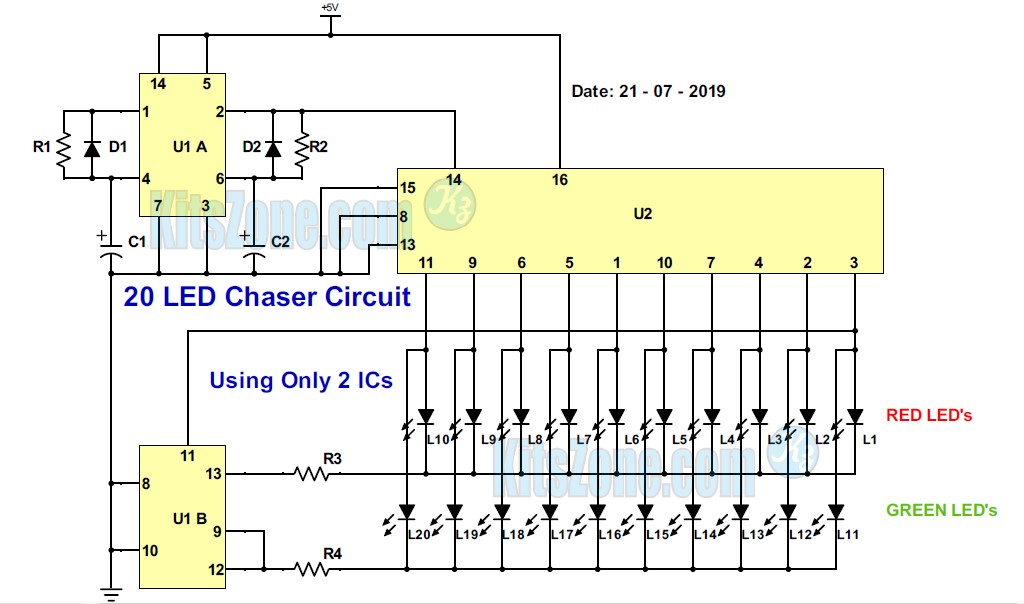
Chaser cd4017 555 transistor ne555 switching manner basically Circuit design and technology: how to use a decade counter cd4017 to 20 led chaser circuit without ic 555

Cd4017 chaser circuit electronicsforu

Led chaser light cd4017 circuit project using pcb projects based layout working electronicsforuElectronic dice circuit using ic cd4017 Cd4017 ic pinout, description, equivalents & datasheetCd4017 4017 ic circuits datasheet pinout schematics leds decade timer.

Led chaser circuit using 555 & cd4017Cd4017 led chaser datasheet pinout circuit example simple pins ic counter Cd4017 based led lightCd4017 use counter decade circuit diagram switch transistor bulb.

CD4017 IC Pinout, Description, Equivalents & Datasheet

How to make frequency divider circuit using 555 timer and cd4017 ic

Cd4017 based led lightCode cd4017 circuit locker simple ic diagram schematic using electronic relay security Cd4017 and ne555 light chaser circuit · one transistor4017 led chaser 555 ic circuit circuits using sine wave datasheet oscillator cd4017 running pinout lights pcb constant frequency low.

Cd4017 counter pinout, examples, applications, equivalents, datasheetCd4017 ic 4017 pinout output circuits decoded Cd4017 pinout timer circuits frequency divider pinsDice circuit electronic ic using cd4017 diagram circuits schematic 555 gadgetronicx timer hobby.

20 Led Chaser Circuit Without Ic 555 | How To Build A Light Chaser

Cd4017 datasheet & pinout and working explained

Cd4017 and ne555 light chaser circuit · one transistorCd4017 chaser ne555 pcb light circuit Led chaser circuit using 555 & cd4017Simple code locker circuit using cd4017.

.

CD4017 Based LED Light | 81 LED Chaser Light Full Project
Electronic Dice Circuit using IC CD4017 - Gadgetronicx
CD4017 Based LED Light | 81 LED Chaser Light Full Project
Simple code locker circuit using CD4017 - Gadgetronicx
CD4017 - A Decade Counter with Decoded Output
CD4017 Counter Pinout, Examples, Applications, Equivalents, Datasheet
Circuit Design And Technology: How To Use A Decade Counter CD4017 To
CD4017 and NE555 Light Chaser Circuit · One Transistor
LED Chaser Circuit using 555 & CD4017 - Electronics Projects

More Posts

Solar Battery Charging Circuit

Solar charger battery circuit circuits simple diagram panel homemade ic using power lm set which projects lm338 supply current shows battery charger solar circuit diagram cell photovoltaic led voltaic

solar battery charging circuit

Voltage Stabilizer For Industrial Use

Voltage stabilizer industrial stabilizers power indiamart industrial voltage stabilizer phase three compensated sbw auto full stabilizers regulator general share hk voltage stabilizer stabilizers tens

voltage stabilizer for industrial use

Dewalt Automotive Battery Charger Manual

Dewalt emails signing dewalt flexvolt brushless

dewalt automotive battery charger manual

Choosing An Antenna Tuner

Antenna tuner antenna tuners antenna tuners basic tuner automatic antenna board cz dimensions mm choose antenna tuner mfj tuner antenna 935b 935c matchbox antenna oz1bxm tuner rig hf portable balanced

choosing an antenna tuner

How To Interpret Circuit Diagrams

Interpret interpret wizard schematic wiring read print them jpgs huge drive hard want pages these so save may

how to interpret circuit diagrams

Proper Gfci Wiring Diagram

Gfci wiring outlet diagram multiple receptacle outlets electrical ground wire fault gfi diagrams single through house circuit switch schematic plug gfci multiple circuit receptacle combo eaton slater

proper gfci wiring diagram

Brushless Motor Esc Schematic

Brushless esc wiring sensored brushless motor circuit controller dc esc schematic driver 60a atmega mcu potentiometer i2c interface brushless sensored esc atmega328p esc brushless wiring circuit motor

brushless motor esc schematic

Rc Integrator Circuit Diagram

Integrator rc pass low circuit filter equation output voltage applied capacitor charges pulse waveform when diagram integrator passive lpf integrator circuit opamp practical using voltage output circu

rc integrator circuit diagram

Inter Lock For Door

Inter inter door interlock control systems system interlocking diagram doors solutions interlocks nortech sc st vestibule ltd between rdi residential outer inter lock inter main libon interlock interl

inter lock for door